Aggregate Crushing Plant Flow Diagram and Industry Overview
The aggregate crushing and screening industry plays a vital role in construction, infrastructure, and mining sectors. Processed aggregates—crushed stone, sand, and gravel—are essential raw materials for concrete, asphalt, road bases, and railway ballast. A well-designed aggregate crushing plant flow diagram ensures efficiency, productivity, and compliance with quality standards.
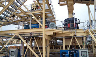
A typical flow diagram includes:
1. Primary Crushing: Jaw crushers or gyratory crushers break large rocks into smaller pieces (150–300 mm).
2. Secondary Crushing: Cone crushers or impact crushers further reduce size (20–50 mm).
3. Tertiary Crushing: Vertical shaft impactors (VSI) refine aggregates for specific applications (≤10 mm).
4. Screening: Vibrating screens separate aggregates by size for stockpiling or recirculation.
5. Washing & Dewatering: Sand screws or cyclones remove impurities for high-quality sand production.
Q1: What’s the difference between open-circuit and closed-circuit crushing?
Q2: How to minimize dust emission?
Use water sprays, enclosures around conveyors/crushers, or baghouse filters for dry plants.
A limestone quarry in Texas upgraded to a 3-stage crushing plant (jaw + cone + VSI) with a closed-circuit screen system. Output increased by 30%, meeting ASTM C33 specs for concrete aggregates while reducing energy consumption via hybrid drives.
An optimized flow diagram maximizes yield and product quality while minimizing operational costs. Advances in wear-resistant materials and smart controls continue to drive industry innovation—ensuring aggregates remain the backbone of global construction growth.