The Role and Breakdown of a Ball Mill in Aggregate Processing
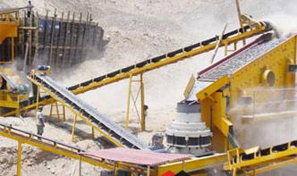
The aggregates and sand industry is a cornerstone of modern construction, providing essential materials for infrastructure, concrete, and road building. Central to this sector is the ball mill, a robust grinding machine widely used to reduce raw materials like limestone, granite, or basalt into fine powders or sand-sized particles.
A ball mill operates on a simple yet effective principle:
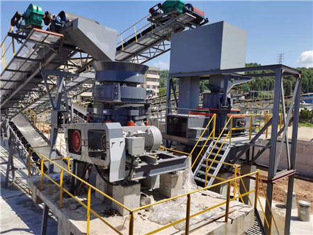
1. Cylindrical Shell: A rotating drum lined with wear-resistant materials (e.g., manganese steel) houses grinding media (steel or ceramic balls).
2. Feed & Discharge: Material enters through one end, while ground product exits via discharge gratings or overflow mechanisms.
3. Grinding Media: Balls cascade and impact the material, crushing it through friction and collision.
4. Drive System: Motors and gears rotate the shell at controlled speeds (critical speed is ~70–80% of rotational velocity for optimal efficiency).
Q: How is ball mill efficiency optimized?
A: Adjusting ball size, material feed rate, and rotational speed ensures maximum output with minimal energy waste.
Q: What maintenance is required?
A: Regular inspection of liners, lubrication systems, and grinding media replacement prevents downtime.
A quarry in Texas replaced traditional vertical shaft impactors with a ball mill circuit, achieving 20% higher sand yield and reduced oversize particles. The system’s adaptability to varying ore hardness proved critical for consistent output.
By understanding its schematic and operational nuances, the ball mill remains indispensable in aggregates processing—balancing precision, durability, and scalability for modern demands.